Low input power led panels with extended lifespan
Low input power led panels with extended lifespan
Page content:
There are various renditions of panels using a LED (Light-Emitting Diode) diode matrix and these panels can have different consumption while illumination is the same. LED panels supplied by our company (stop or vehicle panels) are designed as low input power and are based on the principle of diode voltage regulation which saves significant amounts of energy.
Introduction
How can we ensure low input power of LED panels and extend their lifespan at the same time? There is a number of solutions:
- By using high illumination LED diodes (usually the higher the illumination the longer the lifespan, however, this increases the price).
- By using voltage regulation for situations when it is not necessary to have high dropout voltage at drop resistance and LED diodes.
- Lowering the number of lines or columns in a multiplex lowers the necessary current going through LED diodes.
- By using direct LED diodes with lenses where the luminous flux is concentrated in one direction.
LED panel installment principles – multiplex
For the reasons of lowering the number of components and saving inputs/outputs, luminous diodes are installed in a “time” multiplex while LED diodes are installed into a matrix of lines and columns (see pic. no. 2). The system works as follows : only one line is under current at a time (during one time interval diodes in only one line can be controlled – the corresponding power supply transistor ULED1is switched on) and in the columns it is chosen which diodes are to emit light and in what way they are to do it (given by the data saved in the LED control circuit ). Next another line is switched on and the column setting changes (i.e. different LED are switched on as a result of a new data combination). This system is repeated for the following lines. This line switching happens fast enough to make it impossible for the human eye to notice it (repeat frequency Tmultiplex must be 50 Hz and more).
The advantage of this is a significantly lower number of components, the disadvantage is lowering of service time of individual lines. If the multiplex is designed for 10 lines it means that 1 line shines for Tline = 1/10 of the repeat frequency time Tmultiplex (i.e. „total time / number of lines“). The human eye perceives point light as a medium value which means that at a given time the point must shine 10x more to shine the same as a point without multiplex. As a result of the shortened power supply time of a LED diode (its illumination) it is necessary to direct severalfold higher current/voltage to the diode to keep the same illumination. The power supply pulse of a diode can be shortened only until the voltage reaches the maximum value set by the producer.
If the voltage comes close to this set maximum it together with the transition temperature can affect the lifespan of the whole panel.
The installment principle is to be seen in the following picture no. 2 depicting a 5 x 8 LED matrix where individual lines are powered separately with the help of transistors switching on ULED1.

Pic. no.1: The principle of voltage multiplication in a time multiplex – a demonstration of medium voltage going through a LED diode.

Pic. no.2: LED diode multiplex of a 5x8 matrix.
LED diode lifespan
There is a number of factors affecting Led diode lifespan. It depends on the transition temperature (the surroundings), resp. on the dropout voltage when the diode is shining:
Influence of the temperature of the surroundings
.")
Pic.noč.3 The influence of the temperature of the surroundings on the allowed current going through a LED diode in permeable direction (non-degrading features).
LED diode lifespan is given by the temperature of the luminous transition of the diode (resp. the temperature of the surroundings) and by the current IF going through the diode. It is clear from the graph in the picture no. 3 that when the temperature of the surroundings rises the allowed permanent current in the permeable direction is lowered to prevent the degradation of LED diode luminous intensity and also lifespan shortening.
The picture no.3 describes characteristics of two LED diodes with approximately the same luminous intensity 1 Cd at the current of 20 mA. However, the effect of the surroundings on the allowed current is different. LED no. 1 (black line) allows full luminosity at the current of 20 mA without premature diode aging even at the temperature of 100°C (this high- quality diode is used in our VLP 19 LED panels – green color). According to the graph LED no. 2 (red line) can be used with the same current and luminosity only in the temperature of up to 50°C. Full luminosity in higher temperatures causes diode degradation and lifespan shortening.
If a LED panel containing LED no.2 is placed somewhere where it is protected against direct sunlight the panel does not heat up and the probability of the temperature of the board reaching 50°C is minimum. If the panel is not protected against direct sunlight diode boards can heat up to 50°C – 60°C and LED no. 2 will not be usable in this environment.
Effect of voltage on luminous transition
The following picture (no. 5) shows the relationship of dependence of luminous flux intensity Iv on the current IF in 20 mA LED diodes. It is clear from the graph that for the demonstration LED diode type it holds that it shines with 1 Cd intensity at 20 mA current. In other words illumination intensity is directly proportional to the current going through a diode.
The other picture (no. 4) shows the dependence of voltage on the luminous transition of a LED diode and on the current flowing through the diode. It shows the voltage and therefore also the dropout performance grow with the corresponding current.
-
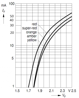
- Pic. no.4: The dependence of the flowing current IF on the voltage VF of a LED diode.

-
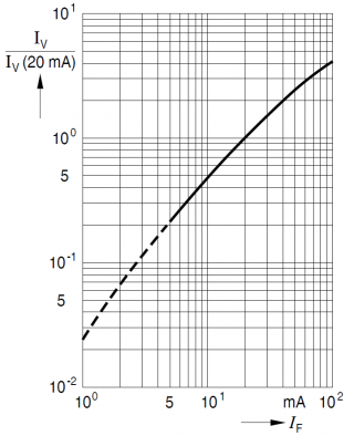
- Pic. no.5: The dependence of LED diode luminous intensity on the flowing current.

Dropout LED performance depending on luminous intensity
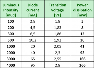
Based on the pictures no. 4 and 5, it is clear that the growth of the dropout performance value depending on luminous intensity is non-linear. It is clear from the table below that higher luminous intensity demands more energy for the diode to shine more. This dependence is to be seen in the picture no. 4 where the vertical axis represents diode luminous intensity in mCd and the horizontal axis represents dropout performance in mW.
This dependence manifests itself negatively especially in multiplex LED diode fields where diodes are switched on progressively in the scope of a time interval and where the diodes must emit e.g. 20 x more energy to achieve the same luminous intensity as without a multiplex (holds for a multiplex 1 :20). For example, if the permanent luminous intensity is 200 mCd the dropout power of a LED diode will be 8 mW with the 1 : 20 multiplex 266 / 20, i.e. 13,3 mW for one diode. The loss on LED diodes is therefore higher (in this case more then 50%) which causes easier diode overheating and therefore rapid aging (the dependence of LED diode light on the flowing current is not linear but it lowers as the current grows).
-
- Pic. No.6:The dependence of LED diode luminous intensity on the power needed to achieve light.

-
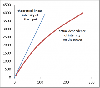
- Pic. no.7: The dependence of luminous intensity on dropout power

Influence of series resistance
As can be seen in the picture no. 2 series resistance is used to balance the current flowing through individual diodes in an installment of a LED matrix. This is necessary since during production it is not possible to ensure that all LED diode transitions have the same features and therefore that diodes shine in the same way with the same voltage VF. On the other hand it is much easier to ensure that LED diodes will shine similarly with the same current IF. Series resistance emulates simple current sources.

Pic. no.8: LED diode installment principle.
What is the main disadvantage of using series resistance? Its dropout power, because the current flowing through it is the same as the current flowing through the diode which means that the bigger the current the higher the loss and further the higher the diode multiplex the bigger the current (see pic. no. 1 showing medium current value).
 and a solution by the Herman company (controlled regulator 2,3V).")
Pic. no.9: Demonstration of a standard solution (source +5V) and a solution by the Herman company (controlled regulator 2,3V).
Losses of series resistance are as follows :
The dropout performance of series resistance for a standard power supply solution +5 V at the current IF = 20 mA and the LED diode voltage UF = 2,2 V is 140 Ohm at Pseries = 56 mW
When a controlled regulator is used (Herman solution) the voltage of the LED diode regulated power supply source is set to 2,3V. With the diode current IF = 20 mA and the LED diode voltage UF = 2,2 V the dropout performance of series resistance is 5 Ohm at Pseries = 2 mW.
This shows a significant power loss of series resistance when the “classic” solution is used and an almost loss free solution for LED panels using accurate voltage regulation produced by the Herman company. This loss is increased even more when a time multiplex is used because the current requirements of series resistance grow even higher.
The following table describes the dependence of LED brightness on dropout power when different line switching time multiplexes are used (duty cycles). The table shows that the bigger the multiplex the higher the dropout power of one luminous point. This is given by the fact that diode voltage grows with bigger current. This effect is increased by using balancing resistance which is placed in a series with LED diodes. These series resistances influence significantly the dropout power of a luminous point.

Pic.noč.10: The dependence of the dropout performance of a luminous point on the LED diode multiplex and on series resistance for the series resistance values of 10 Ohm and 40 Ohm.
*) resistance also includes resistance of switched components (transistors and outputs in control circuits).
The conclusion is simple – the bigger the multiplex of a LED diode matrix the lesser the number of components is used, therefore expenses are lower. The disadvantage of this solution is higher power consumption and shorter lifespan (bigger currents cause faster LED diode aging).
The lower price is therefore outweighed by higher consumption and shorter lifespan. In other words – customers basically pays much more than if they buy better quality panels right at the beginning.
This is the reason why we introduced LED panels with the series resistance of about 5 Ohm and a small multiplex ensuring that losses are much lower than in the case of the classic solution.
Ways of regulating LED panel brightness
As has already been said individual LED panel points are turned on by a “time” multiplex (lines x columns). Duty cycle changes or in the case of our panels also power supply voltage changes (saves energy and lengthens lifespan) can be used to regulate panel illumination.
Brightness regulation using duty cycle changes

Pic. no.11: A demonstration of regulation of medium current flowing through a LED diode
The most often used way of regulating panel LED diode light (stop or vehicle) is changing the duty cycle of power supply voltage in the time of the multiplex on a given line (period Tline..). The original time multiplex interval Třádek. further changes in two subintervals:
Ta - interval, when the power supply voltage is brought,
Tm – interval, when the voltage is turned off.
Thanks to changing the duty cycle of the power supply period – i.e. the ratio of the Ta and Tm intervals – brightness can be simply regulated. When a duty cycle is changed it causes a change of the medium current value which is assessed as a LED light decrease by the human eye although the diode shines the same but for a shorter time.
The power supply regulation solution using duty cycle changes works with the principle that the maximum current needed for maximum LED diode brightness is always flowing through the diode. The current usually corresponds with LED diode light in full sunlight. Light regulation is then performed simply by shortening the interval of current passage.
The performance losses of the system are therefore always maximal and correspond with the values in the table no.2. Panel efficiency does not depend on duty cycles – the loss percentage is almost constant and independent of light and it increases depending on the multiplex – the higher the value – the higher the switched current – the higher the series resistance and LED diode losses.
Higher performance losses cause more heat that must be removed from the panel otherwise its temperature rises causing more rapid aging.
Brightness regulation using voltage change
Why should we precisely regulate LED diode voltage?
Unlike regulation using duty cycle changes, this precise regulation ensures series resistance minimization thus lowering panel losses significantly – see tab. no. 2 where e.g. in the case of the 1:10 multiplex there is a 300 % difference in efficiency !!!
Moreover, when LED voltage regulation is used, the efficiency of the installment rises with lower demanded light – see pic. no. 3 and 4, because the current flowing through series resistance and the diode lowers which also lengthens the lifespan of the diode.
In the case of really dark surroundings when low LED diode light is needed, it is necessary to start also a power supply regulation multiplex because LED diode producers not always guarantee LED diode behavior at very small currents. Thus uneven LED panel light can be prevented – however, this holds for approximately 1/20 of the maximum panel light.
Passive lowering of brightness by choosing LED
One of the important parameters of choosing LED for information panels is also choosing an optical lens. This parameter affects direction of the emitted light and regarding information panels also readability from various angles. Both diode types have advantages and disadvantages therefore it is necessary to know where and how the diode will be used.
This parameter also influences total consumption. The reason for this is reaching the same brightness when LED diodes with the emitting direction characteristics are used (LED with a lens, 90° radiation angle). In the case of diodes with wider radiation angle, higher power input is required to achieve the same brightness as diodes with small radiation angles. Power input rises together with the radiation angle.
Light emitting characteristics of LED produced by the OSRAM company are listed below for the reasons of comparison. The light emitting characteristics clearly show the differences of illumination when LED diodes with lenses with various radiation angles are used. From this follows that e.g. it is convenient to use panels with lenses as front vehicle LED panels and thus save significant amounts of electrical energy.
| Radiation angle | 30° | 55° | 120° |
| Color | Red (625 nm) | Red (625 nm) | Red (625 nm) |
| Voltage in the perm. direction IF= 20mA | 1,8 – 2,4V | 1,8 – 2,4V | 1,8 – 2,4V |
| Brightness | 1650 mCd | 1030 mCd | 750 mCd |
-
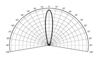
- Pic. no.12: LED with a 30° lens.

-
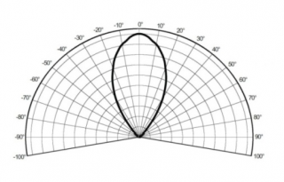
- Pic. no.13: LED with a 55° lens.

-
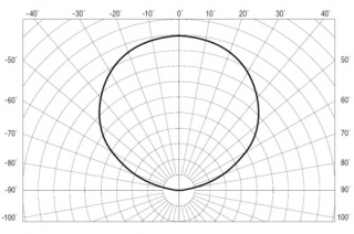
- Pic. no.14: Flat LED diode – 120°.

A comparison of how individual diode types emit light shows significant differences between using LED with a lens and without a lens. The most important difference for LED observers is LED readability from various angles. It is necessary to use LED diodes without lenses (flat LED) with the radiation angle of >90° for information panels designed to display text regardless the angle. Thus the text is visible from broad surroundings. Such panels are suitable for stop information panels.
Herman company LED panel solution
When designing our LED panels (vehicle as well as stop panels) we chose the way of:
- lowering performance losses of series resistance (the value of series resistance is about 5 Ohm) as much as possible and thus lowering the power consumption of the whole panel,
- precisely regulating LED diode voltage (lengthens panel lifespan)
- a small multiplex (to avoid overloading of LED diodes by large currents during the multiplex)
This is the reason why we can guarantee the panel lifespan of 10 years.
Precise regulation – MELP 3x

Pic. no.15:A precise regulated converter MELP - 31.
Our LED panels include the MELP regulated power source (electronic information panel convertor) designed by our company that ensures precise LED diode voltage regulation. The regulator is very efficient (more than 90%) and it does not require cooling (it contains a ventilator to lengthen electrolytic capacitor lifespan).
The MELP regulated power sources of the 3x series are remotely controllable and they can be read out of and set not only from a local control unit but also from dispatching panels thus allowing the user to ascertain LED panel state including the consumed current and the temperature as well as to perform remote configuration. One of the possibilities is the „hot-swap“ mode making it possible for the system to be supplied with power from accumulators in case of a basic power supply breakdown.
| Parameters of the MELP – 3x converter | |
| Input voltage / current | 12V / 20A |
| Output voltage / current | 1,6 – 4,5 V / 70 A |
| Efficiency | >90% |
| Short circuit resistance | YES – Electronic fuse |
| Temperature measuring | Yes (1°C accuracy) – The temperature of the converters is directly proportional to the LED diode light intensity and the temperature of the surroundings |
| Output voltage regulation | in 256 steps |
Energy consumption calculation when the MELP is used
The MELP 3x precise regulation power source allows precise voltage regulation of LED panel diodes.
If an information panel without this regulation is used (8000 LED – panel resolution 50 x 160 points) the emitted power is (0,5 W power loss at one LED diode, as well as the switches and series resistance; multiplex ratio 1:10, power supply +5V):
The emitted power (power loss) can be calculated using the following formula:
Power loss without regulation:
P = number of LED * power loss of one diode / multiplex
P = 8000 * 0,5/10
P = 400 W
However, if our solution with the MELP 3x precise regulator is used it is not necessary to use such high calibrating resistance. The current flowing through a LED diode is only 40 mA with the same luminous intensity (500 mCd) and the 1:4 multiplex. Another difference is that higher current flowing through a LED diode causes a sharp increase of diode voltage. At this luminosity, voltage decreases by 2,2V, i.e. 0,0190 W power loss. Series resistance then loses 0,025W. Therefore the same panel with the same luminosity has the power input of:
Power loss when the MELP-31 is used
P = number of LED * power loss of one diode / multiplex
P = 8000 * 0,09/4
P = 180 W (55% energy saved)
It follows from these calculations that if a suitable diode light time multiplex and precise voltage regulation are used it is possible to save almost half the energy compared with standard solutions supplied by rival companies.
Conclusion
The goal of this article is to show that our panels really are low input power and that their lifespan is extended. Moreover, these features are supported by choosing suitable LED diodes. These diodes themselves guarantee a long lifespan. We avoid degradation and lifespan shortening by not exceeding the limit values.
