Board computers EPIS 5.0A with fare collection
On-board Computers EPIS 5.0x

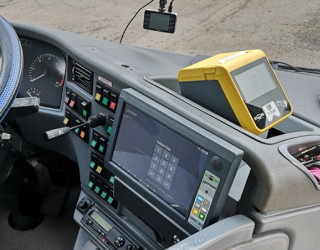
Pic. no. 1: Compact (basic) version of the on-board computer EPIS 5A1 together with the components of checking.
The divided version of the EPIS 5.0 Ax on-board computer with checking for regional public transportation respects the features of OIS control (checking and information system) because it is not always possible to “simply” install the compact version in a vehicle. This is the reason why we offer three basic versions of its mechanical arrangement:
- Compact version EPIS 5.0A1 on one mother board (see pic. no.1) with a docking connector and in a docking version,
- Compact version EPIS 5.0A2 with higher placement of the EPP 5.0A LQB checking unit (see pic. no.2 for buses e.g. SOR),

Pic.no.2: Example of the placement of an EPP 5.0A LQB checking unit in an SOR bus to make it freely accessible to passengers (a version of the EPIS 5.0A2 on-board computer).
- Divided version EPIS 5.0A3, the EPP 5.0A LQB passenger checking unit is placed independently.
The EPIS 5.0Ax on-board computer set contains the following basic parts:
- EPT 5.10A1 or B widescreen LCD terminal with a touchscreen (B is valid when an auxiliary membrane keyboard is not used),
- control unit EPC 5.0 Ax – multiple versions and equipment,
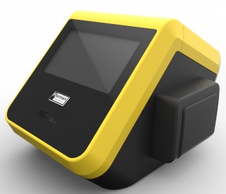
- passenger checking unit EPP 5.0 A LQB, equipped with a printer, a (non-)bank card reader, a QR code reader, and a display for passengers,
- case (drawer) for money,
- simplified power supply unit EPI 5.0Ax (IJN30),
- external identifier of a transportation vehicle.
Composition of an EPIS 5.0 Ax on-board computer set
The parameters of an EPIS 0.5 Ax on-board computer set are based on parameters of the EPIS 4.0C3 on-board computer which are modified to meet the needs of regional public transportation (mechanically and by its equipment). The default front size is the same as terminals EPT 5.10A4 or EPT 5.10Bx (at a request), it can also be different if needed by the customer.
The whole set of the EPIS 5.0 A1 on-board computer (the basic set) consists of the following basic components:
1. High-performance control unit of the EPC 5.0 A1 on-board computer, based on PC computers, with an integrated SSD drive, an LTE modem, a GNSS module (GPC location) and a WiFi module. It also contains an integrated speaker for the driver for voice communication with a dispatching, auxiliary USB 3, USB 2, and 1 Gbit/s ethernet interfaces. The on-board computer is connected via a docking connector (it connects to a connector placed on the money “drawer”).
2. Touchscreen LCD driver terminal - type EPT 5.10A1 - equipped with a microphone, and its own control unit connected to the on-board computer. It is also equipped with an auxiliary membrane keyboard for easier use of the on-board computer and a possibility of using double keystrokes.
3. Checking unit EPP 5.0A LQB connected to the EPC 5.0 A1 control unit of the on-board computer via individual USB interfaces. It forms a mechanical whole consisting of:
- thermal printer for tickets (without a designation – standard equipment),
- contactless bank card reader (designation B), which can also read non-bank card identification, and can be equipped with SAM modules,
- color LCD display for passengers (designation L),
- professional QR reader based on a camera system (designation Q).
4. EPI 5.0A intelligent power supply control unit and one or two power outputs. This unit provides definite vehicle identification i.e. during on-board computer replacement. It is based on tried and tested units IJN used in EPIS 4.0x computers. The unit is/can be a part of the money “drawer”.
5. Drawer for money and a support construction for attaching in a vehicle. It can contain an EPI 5.0Ax unit.
Examples of EPIS 5.0 A1 installation in a vehicle, there are two examples:
- a possible installation in a regional public transportation vehicle can be seen here,
- installation used by IDS JMK here (presented during KORDIS JMK technician training).
Control unit EPC 5.0 A
Basic electric properties of the control unit of the EPC 5.0 A on-board computer:
- control processor – INTEL line E3845 quad-core 40 second start up time (possibility of 1 core – not recommended due to its performance – start up time is 90 seconds)
- Processor speed – standard 1,96 GHz, minimum 1,46 GHz (single-core)
- Memory RAM – standard 2 GB, DDR 3
- Hard memory – SSD disc – 32 GB (different capacity at a request)
- Announcements to the driver – 1x 5W (a part of the on-board computer unit),
- Announcements inside and outside the vehicle – 2x 20W (via the docking connector)
- Microphone – integrated in the head of the touchscreen LCD driver terminal EPT 4.10A4
- Cable connectivity – 2x Ethernet – out of that 1x Gbit/s., 1x 100 Mbit./s, standard IBIS, combined busbar CAN/RS 485, 2x USB 2.0 and USB 3.0,
- Wireless connectivity – modem LTE (up to 100 Mbit/s), module WiFi up to IEEE 802.11 b/g/n/ac (up to 430 Mbit/s)
- Control interface of the unit EPI 5.0 A1(2) (or rather IJN 30)
- One bit inputs/outputs – minimum 4/4
- GNSS – technology SIRF STAR IV – accuracy about 2,5 m (GPS and GLONAS)
- Internal accumulator to remove short-term outages of the power supply from the vehicle on-board network
Touchscreen terminal EPT 5.10
Basic properties of the driver touch screen terminal:
- LCD – 10,1″ widescreen, luminous intensity min. 500 Cd/m2, resolution 1200×800 points
- Touchscreen – thickness 2 mm (1,2 mm also possible)
- Auxiliary illuminated membrane keyboard with remote update indication diodes
- Driver electret microphone for announcements inside and outside the vehicle and for making calls (dispatching or otherwise) via GSM networks.
Parameters of the EPT 5.10A4 driver touchscreen LCD terminal
| Display size | 10,1″ |
| Active surface size | 216 × 135 mm |
| Resolution | 1280 × 800 pixels |
| Brightness | 500 Cd / m2 |
| Touchscreen | Capacity — registering up to 5 simultaneous touches |
| Touchscreen firmness | H7 — glass |
| Illumination regulation | YES — using a photo sensor |
| Lifespan of LCD illumination | 70 000 hours (LED) |
| Auxiliary keyboard | Yes – illuminated, membrane, with indication diodes |
| Driver microphone | Yes – electret |
Mechanical measurements:

Pic. no. 4: Mechanical measurements of the EPIS 5A LCD terminal with an added microphone input and if needed also a non-bank card reader
Customer checking unit EPP 5.0 A – LQB
The mechanic set of the EPP 5.0 A LQB checking unit contains:
- thermal printer for tickets, controlled via PP (on-board computer) using a converter,
- bank card reader is also able to detect non-bank cards – its type depends on the needs of the customer (various types can be supplied); it has a direct connection to PP and the accounting center “acquirera”,
- professional QR code reader with the possibility of displaying the read code to the driver to improve the placement of the reader (passenger movements can be seen on the terminal),
- 4,3″ color passenger display controlled via PP by using a converter,
- possibility of generating sound indication signals for passengers
- slots for up to 4 SAM modules
- paper roll up to 80 mm.
Parameters of passenger checking – EPP 5.0A LQB
| Item | Parameters |
| Passenger LCD display size | 4,3″ |
| Active surface size | 92 × 54 mm |
| Resolution | 480 × 272 pixels |
| Brightness | 500 Cd / m2 |
| Touchscreen | Not included |
| Touchscreen firmness | - |
| Illumination regulation | YES — using s photo sensor |
| Illumination lifespan | 20 000 hours (LED) |
| Printing method | Direct thermal |
| Printing paper width | up to 80 mm (paper width of 3″) |
| Width of printing | up to 72 mm |
| Number of printing points | 576 dots |
| Printing resolution | 8 points / mm (203 dpi) |
| Printing speed (max.) | 250 mm / s |
| Printing lifespan | 150 million pulses |
| Printhead lifespan | 150 km |
| Cutter lifespan | Up to 1,5 million cuts (depending on the paper type) |
| Operation temperature | from – 20 °C to + 70 °C |
| Contactless chip card reader | As per bank standards for EMV cards + MIFARE Classic 1K, 4K and MIFARE DESFire EV1 2K, 4K, 8K |
| SAM module | 2 pieces HW — support of MIFARE SAM AV1 and AV2, other possible via SW (more pieces of SAM modules at a request – 4 and more) |
The EPP 5.0A checking unit is only connected to the EPC 5.0Ax or EPC 4.0x control unit of the on-board computer by one 8-core cable, and it has an independent +24V power supply connection.
Mechanical measurements of the EPP 5.0 A1 checking unit
Thanks to its small size, the passenger checking unit can be placed in a vehicle quite easily:
Module EPI 5.0A
Unit EPI 5.0A is based on our experience with IJN units (Intelligent power supply unit). It is controlled by a data busbar from the EPC 5.0 A1 control unit, and it can measure of the amount of current going into the vehicle from the HS (main switch) conductor and if needed from the PS (auxiliary switch). The unit includes memory determining the definite vehicle identification. Thus, after on-board computer replacement, the on-bard computer is setup based on the vehicle number even including communication with the dispatching (SPRINTER) and the backoffice system (BOS).
Unit contains:
- Input current up to 41 A, divided between the EPC control unit (up to 10 A, peak) and the vehicle (up to 30 A – tableaus, markers, LCD, command receivers, …)
- Power output HS (main switch):
- up to 30 A permanently (HW setting of an electronic fuse)
- 180 A / 800 µs with a fast electronic fuse against overcurrent (power supply short circuit)
- from 5A to 30A for program setting of the output modules. Can be chosen in the FW of the on-board computer.
- Power output PS (auxiliary switch, supplied on a request):
- up to 15 A permanently (HW setting of an electronic fuse)
- 90 A / 800 µs with a fast electronic fuse against overcurrent (power supply short circuit)
- from 3A to 15A for program setting of the output modules. Can be chosen in the FW of the on-board computer.
- Memory for storing the vehicle identification.
Acts as a converter output for ethernet 100 Mbit/s.
Money drawer – attachment in a vehicle
The drawer for money and its support structure are also the support structure of the EPI 5.0 intelligent power supply unit and of the docking connector. It contains a plastic box for money with 6 compartments and it is equipped with a lock. The key is included in the package.
The measurements and attachment in a vehicle are similar to common practices in the Czech Republic.

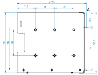
Pic. no.8: Measurements of the installation apertures for attaching the EPIS 5.0A system in a vehicle.
An EPIS 5.0Ax on-board computer displaying a message from the IDS JMK dispatching at night. The picture clearly shows that the dark screen design does not blind the driver at night.
 Site map


